
Flexible printed circuits are not simply rigid PCBs made bendable — they are a fundamentally different substrate technology that changes how you design, assemble, and test your electronics. A rigid PCB can tolerate a 0.15 mm placement offset on an 0201 component without issue. A flex circuit under dynamic bending with the same offset will develop trace cracks within hundreds of cycles, not thousands. The assembly house you select for your rigid boards may not have the tooling, fixture design expertise, or process controls to handle flex circuits at production volumes.
This guide covers what procurement managers and design engineers need to know when transitioning from rigid to flex or rigid-flex PCB assembly: material options and their manufacturing implications, design rules that prevent assembly defects, the three process challenges unique to flex assembly, how inspection requirements change for flexible circuits, and a supplier qualification checklist. It draws on our experience assembling flexible and mixed-technology PCBs at our Shenzhen facility, where flex and rigid-flex now account for an increasing share of mid-volume production runs.
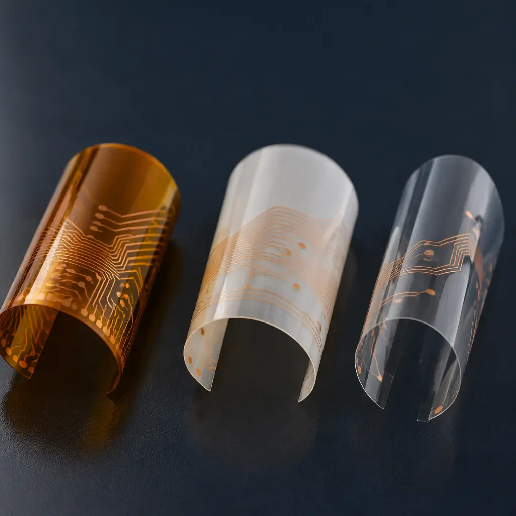
Flex Circuit Materials: The Substrate Decision That Drives Everything
Material choice in flex PCB manufacturing is not a "prefer this over that" decision — it is a constraint cascade. Your substrate selection determines your minimum bend radius, your maximum operating temperature, your assembly reflow profile, and your cost structure all at once.
| Property | Polyimide (Kapton) | LCP (Liquid Crystal Polymer) | PET (Polyester) |
|---|---|---|---|
| Temperature rating | −200°C to +300°C | −40°C to +150°C | −40°C to +105°C |
| Moisture absorption | 1.6–2.8% | 0.02–0.04% | 0.5–0.8% |
| Dielectric constant (Dk) | 3.4–3.8 @ 1 GHz | 2.9–3.1 @ 1 GHz | 3.0–3.2 @ 1 MHz |
| Min bend radius (single-layer) | 3–6× substrate thickness | 2–4× substrate thickness | 5–8× substrate thickness |
| Relative cost | Medium — industry standard | High — specialty applications | Low — consumer/one-time use |
| SMT reflow compatible | Yes (lead-free profiles) | Yes (with controlled ramp) | No — low-temperature only |
Polyimide is the workhorse substrate for 80%+ of flex and rigid-flex assemblies in industrial, medical, and automotive applications. It handles lead-free reflow temperatures (peak 245–250°C) without delamination, survives thousands of dynamic flex cycles when designed correctly, and has an established supply chain with predictable lead times. LCP is the choice for high-frequency applications — 5G antenna substrates, radar modules, millimeter-wave interconnects — where its near-zero moisture absorption and stable Dk across frequency make it worth the 2–3× material cost premium. PET finds its niche in disposable medical sensors, consumer wearables with 12-month product lives, and single-use diagnostic cartridges; it cannot survive reflow soldering and must be assembled with conductive adhesive or low-temperature solder.
Material Cost Reality Check
A 4-layer rigid-flex board with polyimide flex layers and FR-4 rigid sections typically carries a raw material cost 2.5–4× higher than an equivalent all-rigid 4-layer board. The cost driver is not the polyimide itself — it is the yield loss from the more complex lamination process and the additional inspection steps that flexible substrates require. Budget for 85–90% first-pass yield on rigid-flex vs 95–97% on standard rigid boards, and build that into your cost model from day one.
Design Rules That Prevent Assembly Defects
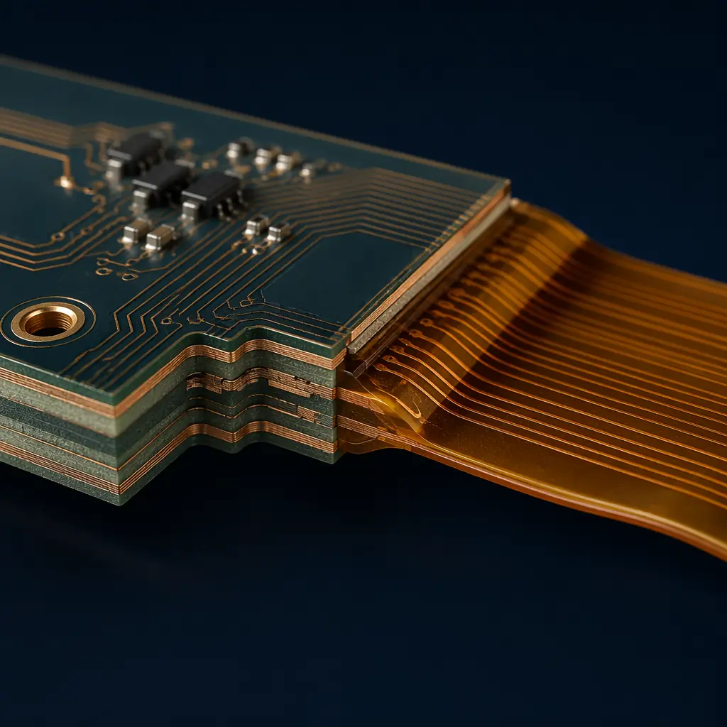
Flex circuit assembly defects cluster around three design mistakes that are invisible in rigid PCB design but catastrophic when the board must bend. Fix these at the layout stage and the assembly yield difference is 5–10 percentage points.
1. Trace routing at the bend zone. Traces crossing a bend line perpendicularly concentrate stress at a single point on each conductor. After 500–1,000 flex cycles, that concentration point develops a micro-crack that propagates into an open circuit. The fix: route all traces perpendicular to the bend axis — curved traces are even better. Keep traces in the neutral bend axis of the stackup, between two ground/power planes when possible, so they experience minimal tensile or compressive strain during flexing. Avoid 90-degree trace corners in bend zones entirely; use radiused corners with a minimum radius of 1.5× trace width.
2. Component placement in rigid-flex designs. Never place components on the flex section — this should be obvious but violations appear routinely in first-revision designs. The flex region is for interconnects only. Components placed near the rigid-flex transition zone (within 3–5 mm) experience asymmetrical stress during reflow because the flex section expands at a different rate than the rigid FR-4. Stagger components away from the transition boundary. For designs using stiffeners (polyimide or FR-4 stiffeners bonded to the flex tail for connector support), treat the stiffened area like a rigid section for placement rules.
3. Pad and via design for flex adhesion. Copper adhesion to polyimide is inherently weaker than copper-to-FR-4 bonding. Annular rings on flex layers should be 0.25–0.3 mm minimum — larger than the 0.15 mm you would use on a rigid board — to compensate for the higher risk of pad lift during rework or connector mating. Teardrop all pads and vias on flex layers. This adds 30 seconds of CAD time and eliminates a failure mode that is nearly impossible to catch in electrical test because the lifted pad will pass continuity right up until the first field flex cycle.
Three Assembly Process Challenges Unique to Flex
Standard SMT assembly lines are designed around rigid substrates that lie flat on conveyor belts, register against mechanical stops, and survive multiple thermal cycles without dimensional change. Flex circuits break all three assumptions.
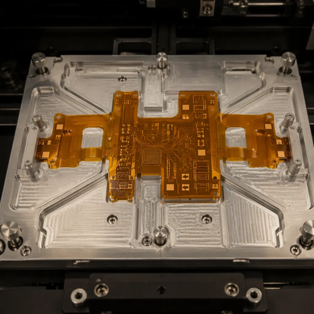
Challenge 1: Fixturing — the substrate won't stay flat. A 0.1 mm polyimide flex circuit placed directly on a reflow conveyor will sag between the conveyor rails, warp during preheat, and shift during placement. The solution is a dedicated carrier pallet — typically aluminum or high-temperature composite — with a precision-machined pocket that holds the flex circuit flat to within ±0.05 mm across the entire assembly area. Vacuum hold-down through the pallet keeps the flex substrate immobilized during printing and placement. For rigid-flex assemblies, the rigid sections provide natural fixturing points, but the flex tail must still be supported to prevent vibration-induced misalignment during high-speed placement. Budget one custom pallet per panel design at $300–800 per pallet, with 50,000+ placement cycle lifetimes.
Challenge 2: Solder paste printing on non-planar surfaces. Even with a carrier pallet, the flex substrate surface is not as uniformly flat as FR-4. Polyimide has a higher coefficient of thermal expansion (CTE: 12–20 ppm/°C vs FR-4's 14–16 ppm in x-y) and absorbs ambient humidity that causes subtle swelling before reflow. This means the 100 µm stencil that prints perfectly on rigid boards may leave inconsistent paste deposits on flex pads. The fix: reduce stencil thickness to 80–100 µm for fine-pitch flex designs, use laser-cut stencils with nano-coating for improved release, and add a post-print SPI (solder paste inspection) step — the 30-second cycle time penalty is cheaper than the rework cost of a single insufficient-paste joint discovered at functional test.
Challenge 3: Thermal profiling for dissimilar materials. A rigid-flex board with FR-4 rigid sections and polyimide flex layers is two materials with different thermal masses and different heat absorption rates going through the same reflow oven at the same time. The FR-4 section may reach liquidus 8–12 seconds before the flex section because polyimide has lower thermal conductivity (0.12 W/m·K vs FR-4's 0.3 W/m·K). The solution: profile the oven with thermocouples on both rigid and flex sections simultaneously, and adjust the soak zone duration so both materials enter reflow within a 3-second window of each other. This typically means extending the soak zone by 10–20 seconds beyond a standard rigid-board profile. For mixed assemblies combining flex circuits with heavy connectors or large BGAs on the rigid section, expect to run 2–3 profile iterations before locking in a production recipe.
Inspection and Testing: What Changes for Flexible Circuits
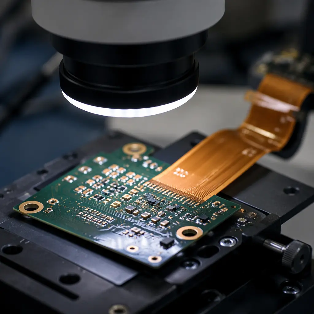
Standard AOI (automated optical inspection) works for rigid sections of a rigid-flex board but struggles with the flex tail — the curved, non-planar surface defeats the fixed-focus optics of most AOI systems. Electrical test (flying probe or bed-of-nails) remains the primary verification method for flex circuit continuity, but it must be supplemented with two additional steps that are not standard for rigid boards.
Cross-section analysis on first-article flex boards. On the first production run of any flex or rigid-flex design, a destructive cross-section through the rigid-flex transition zone should be part of your first-article inspection report (FAIR). This reveals whether the no-flow prepreg used at the transition boundary has properly sealed the interface without bleeding into the flex area — a defect that is electrically invisible but mechanically fatal because cured prepreg in the flex zone creates a stress concentration point that will crack within the first 100 flex cycles.
Dynamic flex cycle testing on production samples. IPC-6013 specifies bend cycle testing for qualification, but production-level sampling is what catches process drift. Pull one board per 500-unit production lot through a bend cycle fixture (minimum bend radius per the design specification, 100,000 cycles for dynamic-flex applications or 10 cycles for flex-to-install). Continuity monitoring during the test catches trace failures that passed electrical test on a flat fixture but fail under mechanical stress. This adds approximately $50 per lot to the quality assurance cost and prevents a field failure that costs 100× that amount in rework, shipping, and customer confidence.
For standard rigid board testing methods — AOI, X-ray for BGA and QFN inspection, ICT, and functional test — these all apply to the rigid sections of rigid-flex assemblies and should be performed at the same frequency as your standard production. The added steps above are flex-specific supplements, not replacements.
Supplier Qualification Checklist for Flex and Rigid-Flex Assembly
Not every PCBA supplier that does excellent rigid board assembly can handle flex. The equipment is the same, but the process controls, fixture design capability, and inspection protocols are different. Here are the five questions that separate flex-capable assembly houses from those that will learn on your production run:
| Question | What to Look For | Red Flag |
|---|---|---|
| 1. Do you have in-house fixture design capability? | Dedicated mechanical engineer with flex pallet portfolio; can show CAD drawings of previous flex fixtures | "We buy standard pallets from our supplier" — one-size pallets don't fit flex designs |
| 2. What is your flex assembly volume in the last 12 months? | ≥50 flex or rigid-flex production runs; can share yield data by design type | "We have done a few prototypes" — prototyping a flex and producing 5,000 units are different skills |
| 3. Do you have a documented flex-specific reflow profile procedure? | Procedure that specifies dual thermocouple placement (rigid + flex), soak zone adjustment rules, and profile validation criteria | "We use the same profile for everything" — this guarantees soldering defects on flex sections |
| 4. What flex-specific inspection steps do you perform? | Cross-section on first article, dynamic bend cycle sampling, AOI on rigid sections with manual visual on flex tails | "AOI covers everything" — AOI cannot handle non-planar flex surfaces |
| 5. Can you provide a flex-capable DFM report before production? | Report that specifically flags flex design issues: trace routing in bend zones, component proximity to transition boundary, pad sizes on flex layers, stiffener design | Generic DFM report with no flex-specific items — they didn't actually review the flex portion |
These questions are not theoretical. When you evaluate a PCB assembly partner in China, the answers determine whether your first production run delivers 95% yield or 75% yield with a three-week delay for fixture redesign and re-profiling. For turnkey flex assembly programs where the supplier also sources flex substrates and stiffeners, add a sixth question: "What is your flex substrate supplier qualification process and how many qualified flex laminators do you maintain relationships with?" Single-source flex laminators create supply chain risk that rigid PCB programs don't face because FR-4 is a commodity with dozens of qualified mills.
Surface Finishes for Flex: ENIG Is Not Optional
Flex circuit pads need a surface finish that provides three things simultaneously: flatness for fine-pitch component placement, corrosion resistance for the flex tail connector interface, and wire-bondability if the design includes chip-on-flex. Among the four main PCB surface finishes, ENIG (electroless nickel immersion gold) is the only finish that delivers all three for flex applications:
| Finish | Flex Compatibility | Reason |
|---|---|---|
| ENIG | Excellent — gold standard for flex | Flat (< 1 µm planarity), corrosion-resistant, solderable after multiple reflow cycles |
| ENEPIG | Excellent — for wire-bonding flex | Adds palladium layer for wire bond pull strength; 30–50% cost premium over ENIG |
| Immersion Silver | Acceptable — short shelf life | Flat surface, but tarnishes within 3–6 months; only use if assembly occurs within 60 days of board fab |
| HASL (lead-free) | Not recommended | Non-planar surface; thermal shock of HASL process can delaminate polyimide adhesive layers |
| OSP | Not recommended | Polyimide adhesion is weaker than FR-4; OSP coating may not uniformly protect flex pads through multiple thermal cycles |
Conformal Coating Note
Flex circuits that operate in humid, condensing, or corrosive environments benefit from conformal coating — but not all coating types are bend-compatible. Acrylic coatings are too rigid for dynamic flex and will crack at bend points. Use silicone-based or ultra-thin parylene coatings (see our conformal coating guide) that maintain flexibility. Coating thickness should not exceed 25 µm on flex sections to avoid adding stiffness that changes the bend characteristics.
Make-or-Buy Decision: When to Transition from Rigid to Flex
Not every product benefits from flex or rigid-flex. The decision to move from rigid boards with connectors and ribbon cables to an integrated rigid-flex design is an engineering economics problem with three variables:
The rigid-flex solution makes sense when: (1) your assembly currently uses ≥2 rigid boards connected by cables or connectors — eliminating those interconnects and their assembly labor typically offsets 60–80% of the rigid-flex board cost premium; (2) your product has a space constraint that a folded rigid-flex design solves — wearable medical devices, compact industrial sensors, and aerospace avionics modules are the classic cases; (3) reliability of the board-to-board interconnect is a field failure driver — replacing a ZIF connector and FPC cable with an integrated rigid-flex transition eliminates a connector mating failure mode entirely.
The rigid solution stays when: your board count is one, your enclosure has ample space, and your board-to-board connections use a single robust connector with a proven field reliability record. Flex assembly adds cost, complexity, and supply chain constraints — it must solve a real design problem, not a hypothetical one.
For high-reliability applications — medical devices under ISO 13485, automotive engine control modules, industrial safety systems — the flex assembly partner you choose becomes part of your regulatory supply chain. Our ISO 13485 and IPC-A-610 Class 3 certifications apply to both rigid and flex assembly programs, with the same traceability and documentation standards across both. If you are evaluating your first flex design transition, factor the assembly partner's flex experience into your lead time planning — a supplier learning flex assembly on your program will add 4–8 weeks to first-article delivery compared to one with established flex process controls.