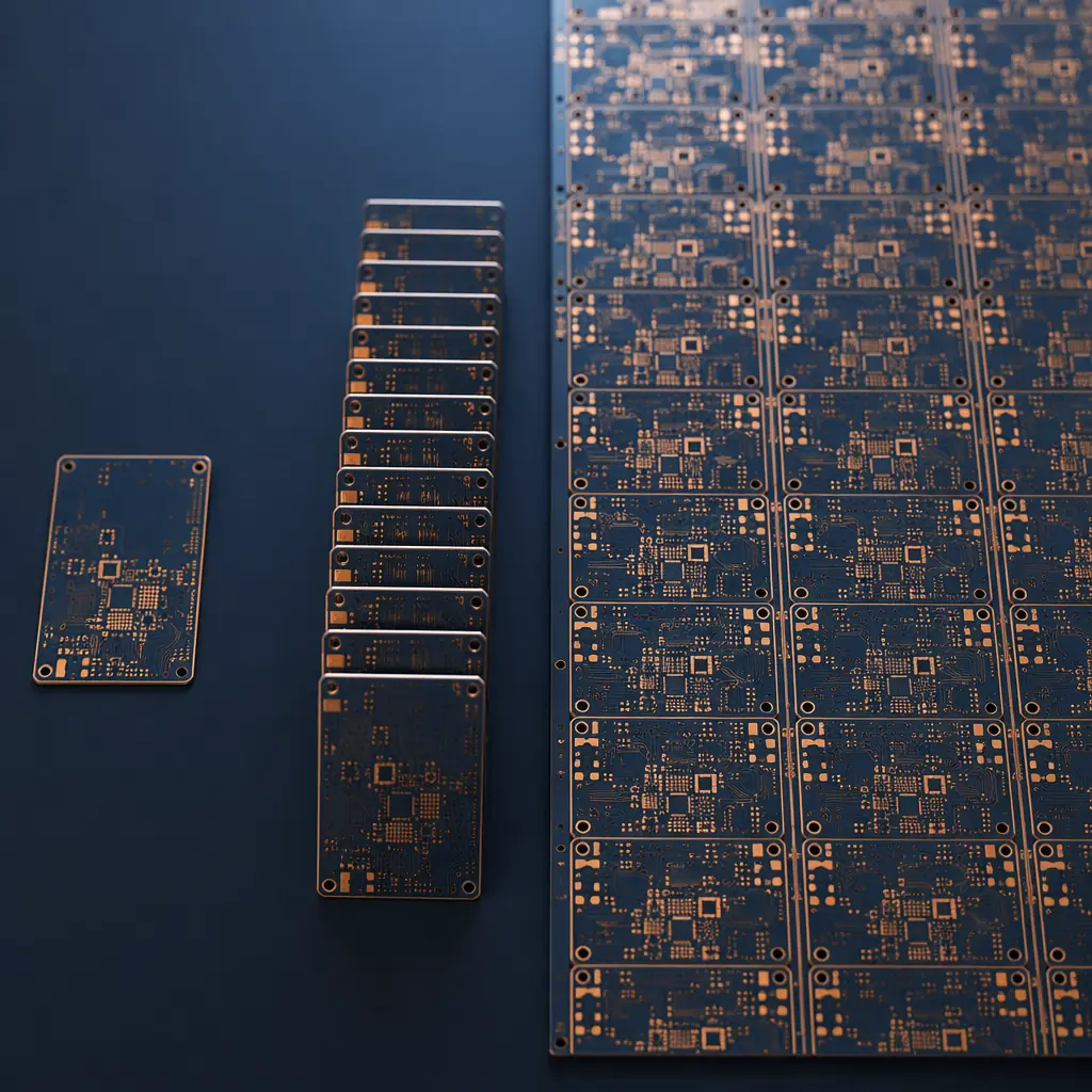
The gap between a working prototype and a production-ready PCB assembly is where most hardware schedules die. Five boards built by hand in an engineering lab work perfectly. One thousand boards coming off an SMT line at 60,000 components per hour — that's a different universe. The transition from prototype to production isn't just a matter of ordering more units. It's a structural shift in how your board gets built, tested, and procured, and every team that underestimates this transition discovers the same thing: the timeline you planned for "just scale it up" was off by a factor of three.
This guide covers the five things that actually change when you cross the prototype-to-production boundary: tooling and fixtures, the inevitable yield dip, minimum viable batch economics, component procurement at volume, and the hidden timeline killers that nobody puts in the project plan. Each section draws on real production data from Uppcba's Shenzhen facility, where we run programs from 5-board engineering builds to 50,000-unit production runs on the same SMT lines.
What Actually Changes When You Go from 10 to 1,000 Boards
A prototype build — 5 to 20 boards — is essentially a manual process with machine assistance. The pick-and-place machine runs, but a technician hand-loads each board, visually inspects every joint, and reworks anything that looks off. The stencil is a single-up laser-cut foil that cost $120 and took two days. Components came from distributor sample programs or small-quantity reels. Testing was a bench power supply and an oscilloscope on an engineer's desk.
A production run — 500 to 5,000 boards — replaces nearly all of that. Here's what shifts, quantified from our production data:
| Process Element | Prototype (5-20 boards) | Production (500-5,000 boards) | Impact on Timeline |
|---|---|---|---|
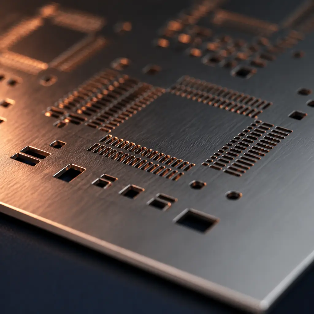
| Stencil | Single-up laser-cut, $120-180, 2-day lead | Multi-up panelized, stepped for mixed components, $300-600, 3-5 day lead | +2-3 days if panelization wasn't designed at prototype stage |
| Solder paste | Type 4 (20-38 μm), hand-applied or single squeegee | Type 4 or Type 5 (15-25 μm) for fine-pitch; automated printer with closed-loop pressure control | Process qualification adds 0.5-1 day for paste-type change |
| Component placement | Offline programming from centroid file, 1-2 hour setup | Online programming with feeder optimization, 4-8 hour setup including feeder loading and nozzle calibration | +0.5 day for full feeder setup on 80+ unique part numbers |
| Reflow profile | Generic lead-free profile, one thermocouple | Board-specific profile with 3-5 thermocouples on representative locations, verified on first article | +0.5 day for profile development and verification |
| Inspection | Manual visual, 100% operator inspection | AOI + manual visual on first article + statistical sampling (AQL 1.0) on production | AOI program creation: 1-2 days for complex boards |
| Testing | Bench test, ad-hoc | ICT/flying probe fixture or functional test station with documented pass/fail criteria | Fixture fabrication: 5-10 working days |
| Conformal coating | Manual spray or brush, if specified | Automated selective coating with programmed keep-out zones | Coating program: 2-4 hours engineering time |
The total delta between prototype and production-ready setup is typically 7-14 working days for a board of average complexity (200-400 components, 6-8 layers, mixed SMT/through-hole). This isn't production time — it's setup time that happens before the first production board enters the reflow oven. Teams that budget zero days for this transition discover it the hard way, usually about three weeks before their target ship date.
The Tooling Transition: Stencils, Fixtures, and Programming You Didn't Budget For
Prototype tooling is simple because the economics are simple: a $150 stencil on a $5,000 prototype build is noise. Production tooling is more expensive not because it's harder to manufacture, but because it's designed to amortize across thousands of cycles without degradation. A prototype stencil lasts 500-1,000 prints before tension loss causes paste smearing. A production stencil, with electroformed nickel construction and nano-coating for paste release, lasts 10,000-50,000 prints — and costs 3-5× more.
Tooling Cost at Scale: The Numbers
A typical mid-complexity board entering production needs: panelized stencil with step-down for fine-pitch ($450), wave solder pallet for through-hole components ($300-600), ICT test fixture or flying probe program ($800-2,500), conformal coating program ($200-400), and AOI program ($300-600). Total one-time tooling: $2,050-$4,550. Amortized across a 5,000-unit run, that's $0.41-$0.91 per board — invisible in the unit cost. But if your run is only 500 units, tooling becomes $4.10-$9.10 per board, which may change your per-unit cost calculation significantly.
The Yield Curve: Why Your First Production Run Quality Drops — and How to Recover
Every first production article has lower yield than the prototype it's based on. This is normal and predictable — but it's also the most common reason procurement managers panic three days into a production run. The yield dip has three causes:
1. Process transfer variation. The prototype was built on one machine, by one operator, with one reflow oven. The production run uses different machines, different operators, and an oven that was last profiled for a different board. Even with identical Gerber files and BOM, the physical process differs. On a recent 2,000-unit industrial controller program at our facility, first-article yield was 92.3% — down from 98.5% on the engineering build. The gap was entirely process transfer: solder paste volume variance (±15% vs. ±8% on the prototype printer), placement offset drift on four 0201 capacitors, and insufficient soak time on a large thermal mass component that the prototype oven handled differently.
2. Component batch variation. Prototypes use components from one reel, one date code, one lot. Production uses multiple reels from multiple lots, potentially from multiple distributors. A reel of 0.1 μF 0402 capacitors from Lot A may have slightly different termination metallization than Lot B, causing a subtle difference in solder wetting behavior. The AOI catches it, but each caught defect is rework time — and rework cost.
3. Operator learning curve. A production technician loading boards every 30 seconds for eight hours develops muscle memory that an engineer building five prototypes never acquires. But that muscle memory takes 50-100 cycles to develop. The first 20 boards of a production run typically carry the highest defect rate — not because anything is wrong with the process, but because the operator hasn't yet internalized the specific handling requirements of this particular board.
Yield Recovery Timeline (Real Production Data)
Based on 47 production launches at our Shenzhen facility over the last 18 months: first-article yield averages 91-94% (vs. 98-99% on the final engineering build). Yield recovers to 97%+ within the first 50-150 boards as process parameters stabilize and operators internalize handling requirements. Full steady-state yield (98.5-99.5%) is typically achieved by board 200-300. The key insight: budget for 5-8% scrap/rework on your first 100 boards. If your production run is 500 units, that's 25-40 boards of rework. The cost of that rework is known and manageable — the cost of not budgeting for it is schedule panic.
Minimum Viable Batch: When Does Automated Assembly Beat Manual?
There's a crossover point where automated SMT assembly becomes cheaper per board than manual or semi-automated approaches. Below that crossover, you're paying for machine time you don't need. Above it, automation's speed and repeatability dominate the economics.
| Board Complexity | Manual/Semi-Auto Crossover | Setup Cost (automated) | Per-Board Savings (above crossover) |
|---|---|---|---|
| Simple (<50 SMD, <5 unique, ≥0805) | ~50-80 boards | $250-400 | $1.20-2.50/board |
| Medium (50-200 SMD, 10-40 unique, down to 0402) | ~30-50 boards | $400-800 | $3.00-6.00/board |
| Complex (200+ SMD, 40-100+ unique, BGA/QFN/0201) | ~15-25 boards | $600-1,200 | $5.00-12.00/board |
The crossover shifts left (fewer boards needed) as complexity increases. A board with a 256-ball BGA and 0201 passives cannot be hand-assembled at any level of reliability — the crossover is effectively at one board. But the practical decision point for most commercial products sits in the 25-100 board range: below that, the setup cost of automated assembly may not amortize across the batch; above it, automation is unambiguously cheaper and more reliable.
For turnkey programs, the minimum viable batch is also influenced by component procurement minimums. A full-reel minimum for a $0.02 resistor buys you 5,000 pieces — far more than a 50-board build uses. In consigned assembly, you carry that inventory cost; in turnkey, the assembly partner absorbs it across multiple client programs.
Supply Chain Scaling: Component Procurement at Volume
The component sourcing strategy that worked for prototype builds collapses at production volume. Prototypes use distributor sample programs, small-quantity reels, and whatever was in stock at DigiKey or Mouser on the day you ordered. Production needs consistent supply across multiple batches, competitive pricing, and lead time buffers that account for the reality of semiconductor allocation cycles.
Three procurement shifts happen at the prototype-to-production boundary:
1. From spot-buy to scheduled procurement. Prototype BOMs are bought once, on the day the build is authorized. Production BOMs need to be bought on a schedule that accounts for 8-16 week lead times on the longest-lead components. The most common scaling failure: discovering that the microcontroller you used in your prototype has a 26-week lead time at production quantities, and your launch is in 12 weeks.
2. From single-source to dual-source qualification. Prototypes use whatever distributor had stock. Production needs at least one qualified alternate source for every single-source component, because single-source parts become allocation nightmares the moment demand exceeds supply. The process of qualifying an alternate — verifying pin-compatibility, firmware compatibility, and electrical performance — takes 2-4 weeks and must happen before the production BOM is frozen.
3. From purchase-to-order to safety stock. A 5,000-unit production run consumes 5,000 MCUs. If your contract manufacturer maintains a 2-week safety stock of that MCU, a supplier delay of up to 10 business days is absorbed without impacting your delivery date. Safety stock costs money — typically 2-4 weeks of component inventory value — but the alternative is a stopped production line, which costs far more. Our component sourcing guide covers the detailed economics of safety stock, allocation risk buffers, and multi-source qualification timelines.
The Hidden Timeline Killers Nobody Mentions
Every NPI schedule includes time for tooling, component procurement, assembly, and testing. The schedule killers are the things that aren't on anyone's Gantt chart:
| Timeline Killer | Typical Delay | How to Prevent It |
|---|---|---|
| Panelization design wasn't production-ready | 5-10 days | Design panelization during prototype phase — not after. Include breakaway rails, fiducial marks, and tooling holes in the initial PCB layout. A panelization redesign after the board is proven adds a full fab cycle. |
| BOM contains obsolete or NRND components | 2-8 weeks | Run a full BOM scrub against distributor databases before freezing the production BOM. Components marked "Not Recommended for New Design" (NRND) that worked fine in your prototype may have zero stock at production quantities six months later. |
| Test coverage gap — prototype passed but production can't be validated at scale | 3-6 weeks for fixture fab | Design test points into the PCB layout during prototype. Adding test pads after the fact requires a board spin. A board without test points cannot be validated at production speed — every unit becomes a manual bench test. |
| Regulatory certification wasn't planned for production changes | 4-12 weeks | If you change PCB suppliers, laminate material, or solder mask chemistry between prototype and production, your FCC/CE/UL certification may need re-validation. Lock the supply chain before certification testing. |
| DFM issues that didn't matter at prototype volume suddenly matter | 1-3 weeks | A 0.3mm pad-to-pad clearance that passed visual inspection on 10 boards produces a 3% short-circuit rate at 1,000 boards. DFM review at production scale catches these before they become yield problems. |
| Programming/test fixture wasn't ordered in parallel with components | 5-10 days of idle line time | Order ICT fixtures, programming jigs, and functional test stations at the same time as your long-lead components. Test equipment lead times (5-15 working days) are comparable to component lead times — don't serialize them. |
The common thread: every one of these timeline killers was preventable with decisions made during the prototype phase, before anyone was thinking about production. The single highest-leverage action a hardware team can take is to run a production-readiness review while the prototype is still being tested — not after it's proven and the launch clock is already ticking.
How to Write an RFQ for Production Scaling
When you send an RFQ to a contract manufacturer for production volumes, include information that a prototype RFQ doesn't require. A prototype quote can work from a BOM and Gerbers. A production quote needs to understand your forecast, your tolerance for lead time risk, and your expected ramp profile.
| # | RFQ Element | What to Include |
|---|---|---|
| 1 | Volume forecast | First production batch quantity + estimated annual volume + expected batch frequency (e.g., "2,000 units initial, 8,000/year in quarterly batches of 2,000") |
| 2 | Ramp profile | How fast you expect to scale: single step (prototype → full production) or phased (100 → 500 → 2,000 over 3 months) |
| 3 | BOM with lifecycle status | Full BOM annotated with component lifecycle status (active/NRND/EOL), preferred manufacturer part numbers, and acceptable alternates if qualified |
| 4 | Test requirements | What testing happens at the CM (ICT, flying probe, functional), what test equipment you'll provide vs. what you need the CM to build |
| 5 | Special process requirements | Conformal coating, press-fit connectors, selective soldering, underfill, thermal interface material application — anything beyond standard SMT reflow |
| 6 | Quality requirements | IPC class (2 or 3), AQL sampling level, any customer-specific inspection criteria, first-article inspection requirements (FAI per AS9102 if aerospace) |
A well-structured production RFQ gets you a quote that reflects actual production economics, not prototype economics. The difference matters: a production quote that assumes 10-board prototype tooling will be $0.50-1.50/board lower than reality because it doesn't include the panelized stencil, production fixtures, or test equipment your volume actually requires. Sending the full picture in the initial RFQ eliminates the re-quote cycle that costs 3-5 days and erodes confidence on both sides.
Prototype to Production Is a Mindset Shift, Not a Volume Shift
The teams that scale PCB assembly smoothly share one characteristic: they treat the prototype-to-production transition as a distinct phase with its own budget, timeline, and decision gates — not as "the same thing, but more." They design for production during the prototype phase (panelization, test points, DFM-optimized layouts). They run a BOM scrub before freezing the production bill of materials. They order test fixtures in parallel with components rather than serially. And they budget 7-14 working days of setup time between the last prototype build and the first production article — not as contingency, but as a planned line item.
The alternative — treating production as a simple volume multiplier — works until it doesn't. When it doesn't, the cost is measured in weeks of schedule delay, tens of thousands of dollars in idle line time, and a launch date that slips past the trade show, past the customer commitment, past the revenue quarter it was supposed to capture.
If your team is approaching the prototype-to-production transition, a PCBA partner that runs both prototype and production volumes on the same lines eliminates the process transfer variables that cause the yield dip. When the same technicians, same machines, and same quality system handle your five-board engineering build and your 5,000-unit production run, the learning curve flattens and the yield recovers within the first 30-50 boards rather than 150-200. At Uppcba, our Shenzhen facility is set up explicitly for this NPI-to-production continuum — prototype programs run on the same SMT lines as production, with the same IPC-A-610 Class 3 trained inspectors and the same AOI/X-ray equipment, so your production launch inherits the process knowledge accumulated during engineering builds rather than starting from zero. Contact our engineering team with your Gerber files and production forecast for a detailed scaling quote within 24 hours.