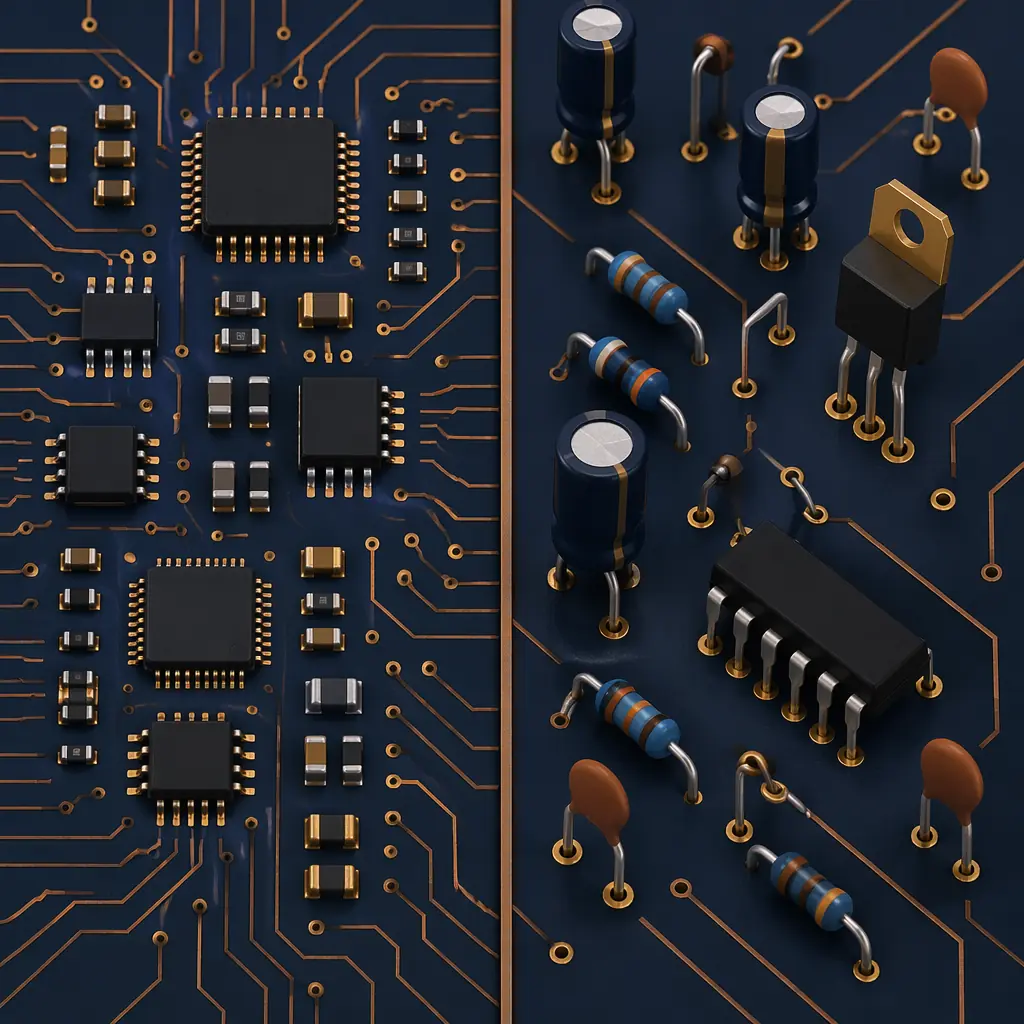
Every PCB assembly project starts with a decision that shapes cost, reliability, and production speed: which assembly process should you use? Surface mount technology (SMT) dominates modern electronics, but through-hole technology (DIP) remains essential for connectors, high-power components, and applications where mechanical strength matters. And many boards need both — a mixed-technology approach that combines SMT speed with through-hole durability.
At Uppcba, we assemble boards across all three process types for clients in 18 countries, from 5-unit prototypes to 5,000-unit production runs. This guide walks through the decision framework our engineers use to recommend a process for each project — based on component types, production volume, reliability requirements, and cost targets.
Surface Mount Technology (SMT): The Workhorse of Modern PCB Assembly
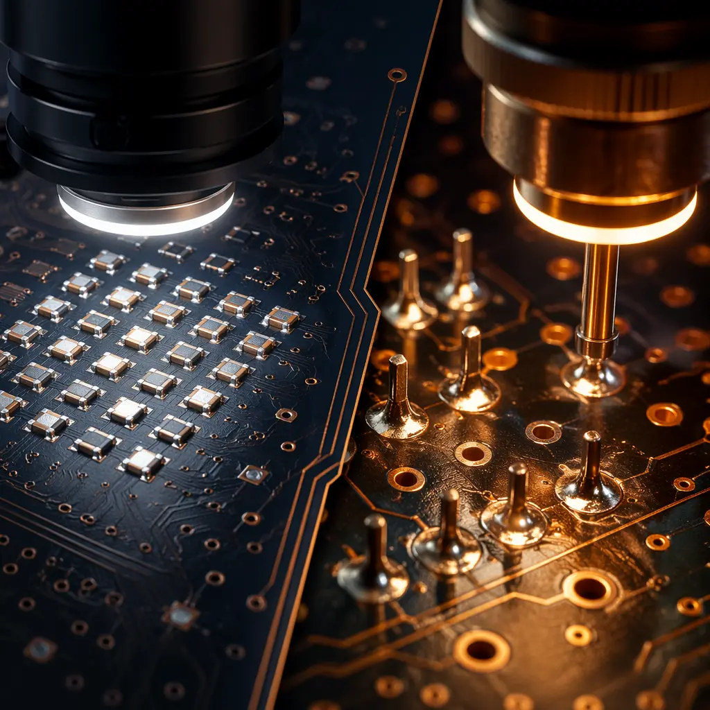
SMT places components directly onto the surface of the PCB — no drilled holes, no leads through the board. Components are held in place by solder paste, which is printed through a laser-cut stencil, then reflowed in a controlled oven. The entire process is automated from paste printing through optical inspection.
The throughput advantage is substantial: a modern SMT line at Uppcba places 40,000 to 60,000 components per hour across multiple pick-and-place heads. For a typical mid-complexity board with 150 components, that translates to roughly 9 seconds of placement time per board — not counting paste printing and reflow, which run in parallel. This throughput is the reason SMT dominates production volumes above 100 units.
SMT also enables miniaturization. Components as small as 0201 (0.6 mm × 0.3 mm) are standard on our lines, and we routinely handle 0.4 mm pitch BGAs and 0.5 mm pitch QFPs. The absence of drilled leads means both sides of the board can be populated — double-sided SMT effectively doubles the component density without increasing board area.
Choose SMT when: your components are surface-mount packages (SOIC, QFP, BGA, 0402–1206 passives), your production volume exceeds 100 units, board size is constrained, or you need the lowest per-unit assembly cost at volume.

Through-Hole Technology (DIP): When Mechanical Strength Matters
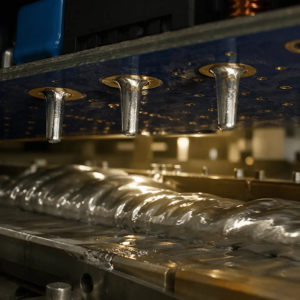
Through-hole assembly inserts component leads through drilled holes in the PCB, then solders them — either by wave soldering for batch processing or by hand for low-volume and prototype work. The resulting solder joint wraps through the board, creating a mechanical anchor that SMT joints cannot match.
This mechanical advantage is not subtle. In vibration testing per IEC 60068-2-6, through-hole connectors routinely survive 10G vibration levels where equivalent SMT-only connectors begin showing joint cracks at 5G to 7G. For automotive under-hood electronics, industrial motor controllers, and aerospace power supplies, this difference is the margin between field reliability and field failure.
Through-hole also handles current better. A typical through-hole pin in a TO-220 power package can carry 5A to 10A continuously, where an equivalent SMT pad on the same package is limited by trace width and thermal dissipation through the board surface. For power supply designs above 50W, through-hole output components often eliminate the need for additional copper weight or external heatsinking.
Choose through-hole when: your design uses DIP ICs, axial/radial passives, connectors with mechanical insertion force, power transistors (TO-220, TO-247), or any connector that will experience repeated mating cycles in the field.
Mixed Assembly: When One Process Is Not Enough
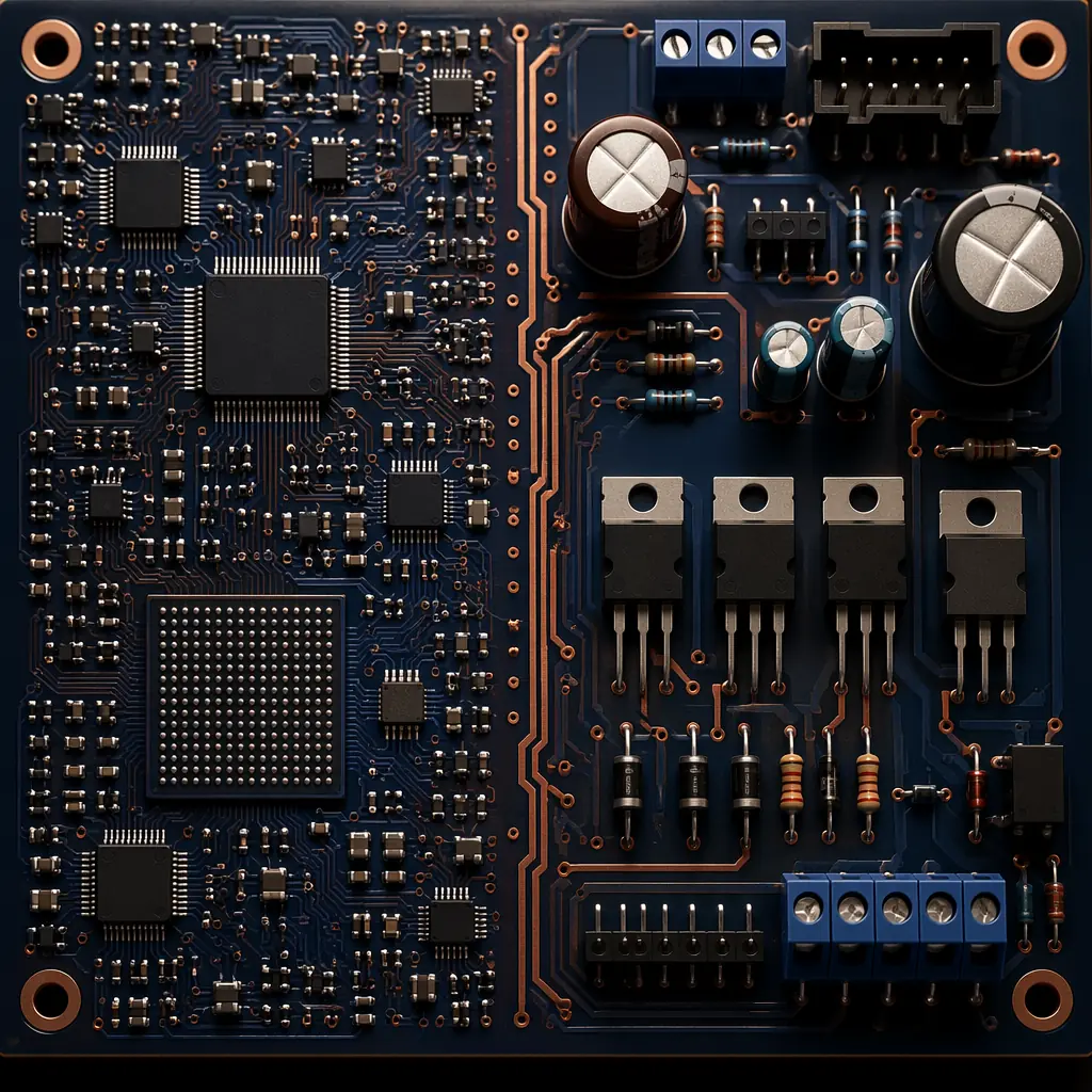
The reality for most real-world designs is that neither pure SMT nor pure through-hole is sufficient. A motor controller might use surface-mount microcontrollers, op-amps, and passives for the control section, but through-hole MOSFETs and screw terminals for the power stage. An industrial sensor might pack signal conditioning into SMT ICs but require a through-hole connector for field wiring. These are mixed-technology boards, and they represent roughly 40% of the projects we assemble at Uppcba.
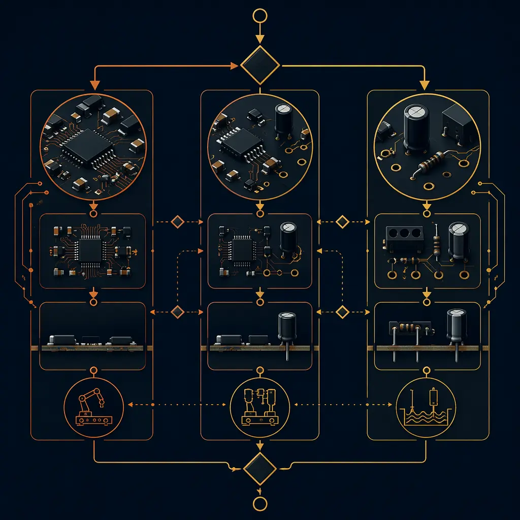
The mixed assembly process runs in two sequential passes. First, surface-mount components are placed and reflowed as in a standard SMT run. Then, through-hole components are inserted — either by hand for low volume or by selective soldering machine for higher volume — and soldered. The second pass adds process time: roughly 30 to 60 minutes per batch for wave soldering with fixture loading, or 2 to 4 seconds per joint for selective soldering. This additional time is the cost of getting both SMT density and through-hole durability on the same board.
Key consideration for mixed assembly: through-hole components must survive the SMT reflow profile — typically peaking at 240°C to 250°C for lead-free solder. Most connectors and power devices are rated for this temperature, but electrolytic capacitors, relays, and some switches are not. If a through-hole component cannot survive reflow, it must be placed after SMT in a second manual or selective soldering step, which increases labor cost per board.
Decision Matrix: Which Components Drive Which Process
The simplest way to determine your assembly process is to inventory your BOM by package type. The component types on your board — not your preference — drive the process decision. Here is the decision logic our engineers apply to every incoming design:
| If your BOM contains… | Required Process | Notes |
|---|---|---|
| Only SMT packages (SOIC, QFP, BGA, chip passives) | SMT only | Fastest throughput, lowest per-unit cost at volume |
| Only through-hole packages (DIP, axial, TO-220) | Through-hole only | Rare for new designs; mostly legacy or high-power |
| Mix of SMT and through-hole | Mixed assembly | Two-pass process; ~40% of our projects |
| Through-hole connectors rated for reflow | SMT + pin-in-paste | Single-pass; avoids second soldering step |
| BGA + through-hole power devices | Mixed + X-ray inspection | BGA needs X-ray; through-hole needs wave or selective |
| Fine-pitch (≤0.5 mm) + large connectors | Mixed + stencil optimization | Step stencil recommended for varied paste volume |
The pin-in-paste option deserves special attention. If your through-hole connectors are rated for reflow temperatures — increasingly common with newer connector families — you can print solder paste into the through-holes during the SMT paste printing step, place the connector alongside SMT components, and reflow everything in a single pass. This eliminates the entire second soldering step and its associated time and cost. We recommend pin-in-paste whenever the connector datasheet confirms reflow compatibility above 245°C for 30 seconds.
Cost Comparison by Process and Volume
Process choice directly affects per-unit cost, and the relationship changes with volume. SMT has higher upfront tooling cost — the stencil alone runs $80 to $150 for a laser-cut stainless steel foil — but the per-unit assembly cost drops rapidly with quantity because placement is fully automated. Through-hole has lower tooling cost but higher per-unit labor, especially for hand-soldered boards. Mixed assembly sits between, with two sets of tooling and two process steps.
Based on our production data, here are representative per-unit assembly costs for a mid-complexity board with 120 components, excluding component procurement:
| Volume | SMT Only | Through-Hole Only | Mixed (70% SMT) |
|---|---|---|---|
| Prototype (5 units) | $120–180/board | $90–140/board | $150–220/board |
| Low-volume (100 units) | $18–25/board | $25–35/board | $22–32/board |
| Mid-volume (1,000 units) | $5–8/board | $18–25/board | $8–14/board |
| Production (5,000 units) | $2–4/board | $14–20/board | $5–9/board |
At prototype quantities, the cost differences between processes are compressed — setup and programming time dominates over per-unit placement time. At 5,000 units, SMT's automation advantage creates a 5x to 7x cost gap versus through-hole. This is why high-volume consumer electronics are almost entirely SMT, and why through-hole persists primarily in low-volume industrial, automotive, and aerospace applications where mechanical reliability justifies the cost premium.
Quality and Inspection: Different Processes, Different Failure Modes
Each process brings its own inspection requirements because the dominant failure modes differ. SMT failures are dominated by solder paste issues — insufficient paste, bridging between adjacent pads, and tombstoning of small passives. Automated Optical Inspection (AOI) catches these inline, processing roughly 2 to 5 minutes per board. Our AOI system checks every solder joint against a golden-board reference, flagging deviations in joint shape, size, and position.
Through-hole failures shift toward hole fill and mechanical issues: insufficient hole fill (barrel fill below 75% per IPC-A-610 Class 3), lifted pads from excessive thermal stress, and cracked joints from mechanical load. Visual inspection with magnification catches most through-hole defects, but X-ray is sometimes required for multi-layer boards where internal pad connections are not visible from the surface.
For mixed-technology boards, the inspection challenge is that both failure modes coexist on the same board. Our standard quality workflow for mixed assembly includes AOI for the SMT portion, visual inspection with magnification for through-hole joints, and X-ray for any BGA or QFN packages present. A complete first-article inspection report — including cross-sections if specified — is standard for every new project before production release.
How to Specify Your Assembly Process in an RFQ
When requesting a quote, the process type should be clear — but surprisingly often, it is not. Here is what a complete process specification looks like in a request for quotation:
- Assembly type: SMT only / through-hole only / mixed. If mixed, specify the approximate percentage of through-hole components by pin count.
- Board dimensions and panelization: Single board size and preferred panel format (if any). Include Gerber data with paste mask layers.
- Component list: BOM with manufacturer part numbers and at least one approved alternate per critical component. Flag any components that are not reflow-compatible.
- Inspection standard: Specify IPC-A-610 class (Class 2 or Class 3) and any additional requirements — X-ray for BGA, cross-section for first article, functional test specification.
- Special requirements: Conformal coating, potting, press-fit connectors, or any non-standard process steps.
A clear process specification eliminates the back-and-forth that delays quotations by 2 to 3 business days. When our engineering team receives a complete package matching the format above, the typical quote turnaround is under 24 hours.
Conclusion: Let the Components Decide
The assembly process is not a design choice — it is a consequence of your component selection. Surface-mount components drive SMT. Through-hole components drive DIP. A mix of both drives mixed assembly. The most cost-effective approach is almost always the one that matches your BOM, not the one that seems cheaper in isolation.
If you have a design in progress and are uncertain which process it requires, send the BOM and a draft layout to our engineering team for a free process assessment. We will identify which process matches your component selection, flag any parts that create unnecessary process complexity, and recommend alternatives where available — typically within one business day. That assessment costs nothing and can prevent the most expensive mistake in PCB assembly: choosing the wrong process before you know what your board actually needs.