
A printed circuit board inside a pacemaker, infusion pump, or surgical monitoring system is not just an electronic component — it is a life-safety device subject to regulatory scrutiny that standard commercial electronics never face. When a medical device PCB fails, the consequence is not a returned unit or a warranty claim. It is an adverse event report to the FDA, a potential recall, and — in the worst case — patient harm. This is why medical device PCB assembly operates under a fundamentally different set of requirements than industrial or consumer electronics assembly.
This guide covers the three pillars of medical device PCB assembly that procurement and quality managers need to evaluate when selecting a manufacturing partner: ISO 13485 quality management system requirements as they apply to PCBA, IPC-A-610 Class 3 acceptance criteria and what they mean at the production-line level, and the validation documentation and traceability infrastructure that FDA and Notified Body auditors expect to see during an inspection. Every section draws on our experience assembling medical device PCBs under our own ISO 13485 certification at our Shenzhen facility — where we maintain the same ISO 13485 and IPC-A-610 Class 3 certifications that medical OEMs require.
What Makes Medical Device PCB Assembly Different
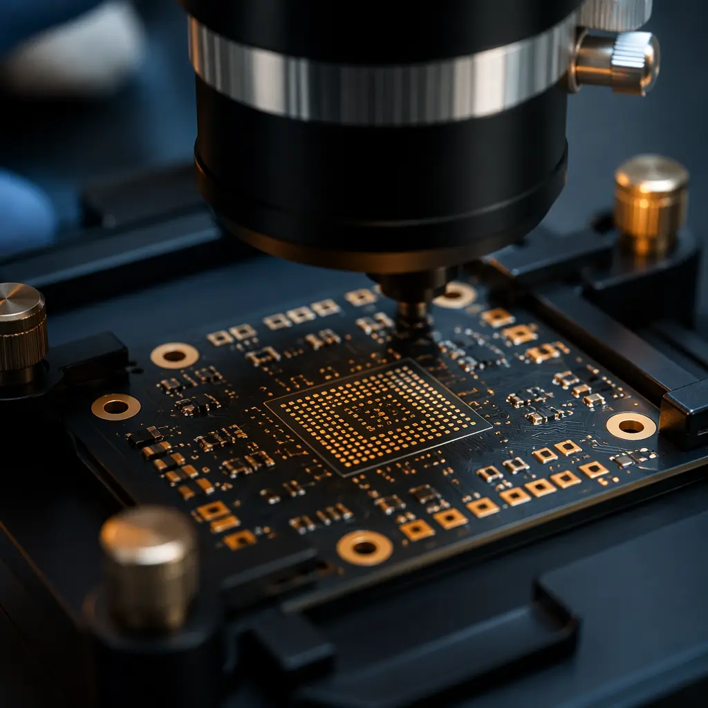
At a process level, SMT assembly for a medical device PCB uses the same core equipment — pick-and-place machines, reflow ovens, wave solder systems — as assembly for any other electronics product. The difference is not in the machines. It is in the controls, the documentation, and the acceptance criteria applied at every stage.
Three structural differences separate medical device PCBA from standard commercial assembly:
| Dimension | Standard Commercial PCBA | Medical Device PCBA |
|---|---|---|
| Quality management system | ISO 9001 — process-based, continuous improvement focus | ISO 13485 — adds risk management (ISO 14971), design controls, regulatory compliance, post-market surveillance |
| Acceptance standard | IPC-A-610 Class 2 — dedicated service electronic products. Allows some visual imperfections | IPC-A-610 Class 3 — high-performance/harsh environment. Zero-criteria on critical defects. Stricter solder joint requirements: 25% less voiding tolerance, tighter fillet geometry |
| Traceability | Lot-level traceability sufficient for most commercial products | Unit-level traceability required: every PCB must be traceable to its specific component lots, solder paste batch, reflow profile data, inspection records, and test results — typically via unique serial number assigned at first process step |
| Change control | Process changes documented but not always customer-notified | Every process change — including solder paste brand substitution, reflow profile modification, or inspection equipment replacement — requires documented customer notification and, in many cases, re-validation before implementation |
| Documentation retention | Typically 2–3 years for commercial products | Minimum 10 years post-production (FDA QSR 21 CFR Part 820.180), often 15+ years for implantable devices |
The practical consequence of these differences is that a PCBA manufacturer serving medical device customers must operate two parallel systems: the production system that assembles boards, and the compliance system that generates the evidence trail proving every board was assembled correctly. The compliance system costs roughly 15–25% more to operate than a pure-production ISO 9001 line — a cost that must be factored into medical device assembly pricing but is non-negotiable for regulatory compliance.
ISO 13485 Requirements That Apply Directly to PCBA
ISO 13485:2016 is the international standard for medical device quality management systems. While the standard covers the full device lifecycle, several clauses have direct and specific implications for PCB assembly operations:
Clause 7.5.1 — Control of Production and Service Provision
This is the clause that auditors examine most closely during a PCBA facility inspection. It requires documented work instructions for every production process, equipment qualification records, and controlled environmental conditions. For PCB assembly, the practical requirements include:
| Requirement | What It Means on the Production Floor |
|---|---|
| Documented process parameters for every operation | Solder paste printing: stencil tension (35–50 N/cm²), squeegee pressure (80–150 g/mm), print speed (25–100 mm/s), separation speed (1–3 mm/s). Reflow: documented thermal profile with soak zone (150–180°C, 60–120s), reflow zone (>217°C, 60–90s for SAC305), peak temp (235–250°C). These parameters must be recorded per lot, not just specified once. |
| Equipment qualification and preventive maintenance schedule | Pick-and-place placement accuracy verified monthly via test board (target: ±0.025mm for 0201 components). Reflow oven thermal uniformity tested quarterly (target: ±2°C across conveyor width). Solder paste inspection (SPI) calibrated before each shift. |
| Controlled environment | ESD flooring (<1×10⁹ Ω), relative humidity 40–60%, temperature 22±3°C. Continuous monitoring with alarm thresholds — not spot checks at shift start. |
| Personnel competency records | Each operator must have documented training on the specific equipment and process they operate, with competency re-assessment annually or after any process change. IPC-A-610 certification for all inspection personnel. |
Clause 7.5.6 — Validation of Processes for Production and Service Provision
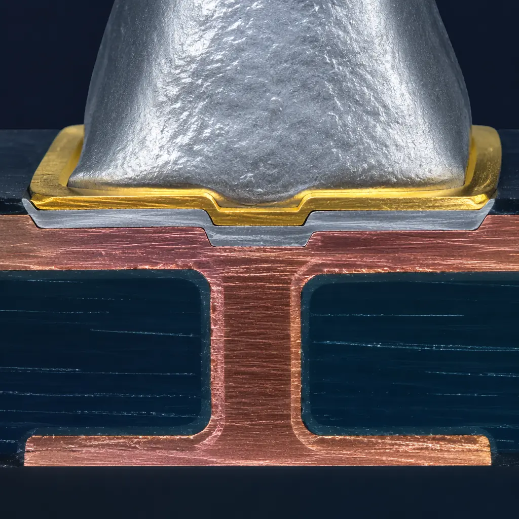
This clause requires that any process where the output cannot be fully verified by subsequent monitoring or measurement must be validated. In PCB assembly, reflow soldering is the textbook example: you cannot 100% inspect the intermetallic bond inside every solder joint without destroying the board. Therefore, the reflow process must be validated — typically through a combination of:
- Thermal profiling on a representative board (minimum 3 thermocouples at different PCB locations)
- Cross-section analysis of solder joints on a sacrificial validation board (target: intermetallic layer 1–3µm at the pad-solder interface, continuous and uniform)
- Statistical process control on key quality indicators: first-pass yield, solder paste volume CpK (target: >1.33 at ±50% tolerance), AOI false-call rate
The Cost of Process Validation vs the Cost of Skipping It
A full reflow soldering validation — thermal profile development, cross-section analysis, SPC baseline, and documentation package — costs approximately $1,200–2,500 per product. A single FDA 483 observation for inadequate process validation triggers a formal response, potentially a re-inspection, and in the worst case a warning letter that can halt production. The average cost of responding to an FDA 483 observation is $35,000–85,000 in consulting, remediation, and management time — roughly 25× the cost of doing the validation correctly the first time. For CE-marked devices, a Notified Body non-conformity has similar cost implications.
IPC-A-610 Class 3: What the Acceptance Criteria Mean at the Line
IPC-A-610 is the most widely adopted standard for electronic assembly acceptance. Class 3 — "High Performance Electronic Products" — is the level required for medical devices where continued performance is critical and equipment downtime cannot be tolerated. The standard defines three conditions: Target (ideal), Acceptable (passes but not ideal), and Defect (must be reworked). Class 3 tightens the boundary between Acceptable and Defect across every solder joint characteristic.
Here are the specific Class 3 criteria that most affect medical device PCB assembly yield and cost:
| Characteristic | Class 2 Acceptable | Class 3 Acceptable | Impact on Assembly Yield |
|---|---|---|---|
| Solder joint voiding (BGA/CSP, X-ray) | ≤30% void area per ball | ≤25% void area per ball | Approximately 3–8% of joints that pass Class 2 fail Class 3 on voiding alone. This is the single largest contributor to the Class 2→Class 3 yield gap. |
| Gull-wing lead side overhang (QFP/SOIC) | ≤50% of lead width | ≤25% of lead width | Placement precision requirements increase. 0.5mm pitch QFP placement target tightens from ±0.075mm to ±0.05mm. |
| Chip component end overlap (0201/0402) | ≥50% of termination on pad | ≥75% of termination on pad | Pick-and-place accuracy becomes yield-critical for 0201 components. Placement CpK must be >1.33 at ±0.05mm. |
| Minimum solder fillet height (chip components) | G+25% of H (G=solder thickness, H=component height) | G+50% of H | Requires more solder paste volume — stencil aperture design must compensate with larger openings or step stencils for fine-pitch areas. |
| Blowholes/pinholes in PTH solder | Permitted if not reducing joint strength | Not permitted | Requires tighter control of PCB plating quality and pre-heat profile; outgassing from ENIG or HASL finishes must be fully characterized. |
On a mid-complexity medical device PCB — say, a 6-layer board with 250 components, including a 0.5mm-pitch QFP and two BGAs — the first-pass yield difference between Class 2 and Class 3 criteria is typically 5–12 percentage points. A line running 95% FPY at Class 2 may run 85–90% at Class 3. This yield gap is not a defect; it is the intended consequence of stricter acceptance criteria, and it must be factored into cost modeling for medical assembly programs. The boards that fail Class 3 but would have passed Class 2 are not "bad" boards — they simply do not meet the zero-tolerance-for-failure standard that medical devices require.
Validation Documentation: The Evidence Trail Auditors Actually Check
During an FDA inspection or Notified Body audit of a medical device PCB assembly operation, auditors do not spend much time watching the production line. They spend most of their time in the document review room, tracing individual serial numbers backward through the production record. Here is what they ask to see — and what a compliant PCBA manufacturer must be prepared to produce:
| Document | What It Contains | Traceability Chain |
|---|---|---|
| Device History Record (DHR) | Complete production history for a specific PCB serial number: which component lots were placed, solder paste batch, reflow profile data (time-at-temperature graph), AOI images, ICT/flying-probe test results, any rework performed and by whom | Serial number → all upstream records |
| Incoming inspection records | For each component lot: certificate of conformance from manufacturer, incoming visual/dimensional inspection results, date code verification, moisture sensitivity level (MSL) handling log | Component lot → DHR |
| Process validation report | Solder paste print CpK data, reflow profile validation with thermocouple positions marked on board layout, cross-section images with scale bars, statistical analysis of voiding/IMC thickness | Process parameter → DHR |
| Calibration certificates | Calibration records for SPI, AOI, reflow oven thermocouples, X-ray system, ICT/flying-probe tester — traceable to national standards (NIST/NIM) with calibration interval and next-due date | Equipment → process parameter → DHR |
| Non-conformance report (NCR) | Every defect detected at AOI, ICT, or functional test that required rework or disposition, with root cause analysis (5-Why or fishbone), corrective action taken, and verification of rework effectiveness | Defect → DHR |
Documentation as a Production Cost Driver
A standard commercial PCB assembly run generates approximately 3–5 pages of production documentation per board lot. A medical device assembly run generates 15–30 pages per board — and for Class III implantable devices, the documentation package can exceed 50 pages per unit. This documentation overhead adds an estimated $3–8 per board in labor cost for data entry, review, and filing — fully loaded with the QA personnel time required to maintain the document control system. For a 1,000-unit medical device production run, that is $3,000–8,000 in pure documentation cost. This is not overhead that can be eliminated; it is the cost of being able to prove — with evidence — that every board was assembled correctly.
Traceability Systems: From Lot-Level to Unit-Level
Lot-level traceability — knowing that a batch of PCBs used components from lots X, Y, and Z — is sufficient for most commercial products and is the minimum that ISO 9001 requires. Medical device regulations demand unit-level traceability: the ability to take any single PCB serial number and reconstruct its complete manufacturing history, from incoming component inspection through final test.
A compliant unit-level traceability system for PCB assembly requires three elements:
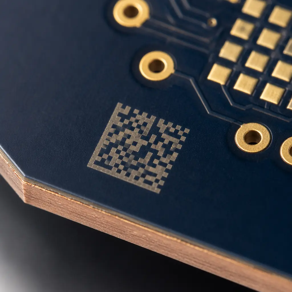
1. Unique device identification at first process step. Each PCB must receive a unique identifier — typically a 2D data matrix code (similar to a QR code but smaller, typically 3×3mm or 4×4mm) laser-etched or inkjet-printed on the board edge — before any components are placed. This identifier must survive all subsequent processes including reflow soldering (peak temperature 235–250°C), aqueous cleaning, and conformal coating if applied. The UID is the key that unlocks the entire Device History Record.
2. In-line data capture at every process node. The UID must be scanned or read at each process step, and the data from that step must be linked to the UID in a database. For SMT assembly, the critical capture points are: solder paste print (SPI results — volume, area, height per pad), component placement (feeder position, placement offset per component), reflow (time-above-liquidus, peak temperature, soak duration per board), AOI (pass/fail per component, defect images), and test (ICT/flying-probe pass/fail, measured vs nominal values).
3. Closed-loop change control integration. If a process change occurs — a solder paste lot change, a reflow profile adjustment, a component alternate approved — the system must link the change to all affected serial numbers. An auditor should be able to query: "Show me every PCB serial number that was assembled with solder paste lot SP-2026-07-14-B." The answer must be available within minutes, not days of manual file searching.
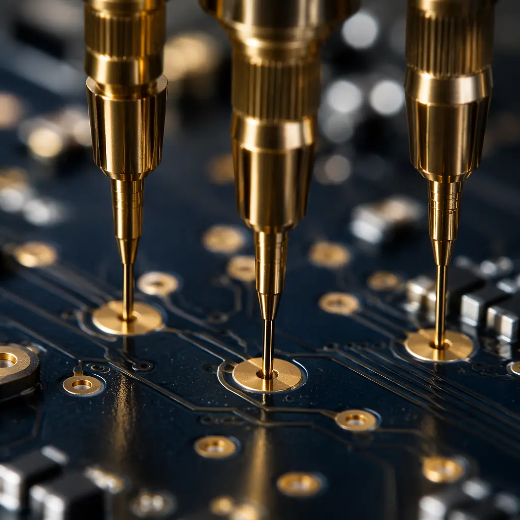
This traceability infrastructure is not a software purchase — it is a process architecture that integrates barcode/2D readers at every inspection station, a manufacturing execution system (MES) or equivalent database, and documented procedures for data entry, review, and archival. A manufacturer claiming unit-level traceability should be able to demonstrate it live during a site visit by pulling up the full DHR for a random serial number from a shipment completed the previous week. If they need more than 5 minutes to produce it, they do not have a working traceability system.
How to Qualify a Medical Device PCBA Partner: The Audit Checklist
Selecting a PCBA manufacturer for a medical device program requires a different evaluation framework than selecting one for a commercial or industrial product. The questions below are designed for an on-site audit or a detailed virtual assessment. A manufacturer that answers these questions with specifics — numbers, documented procedures, demonstration of actual records — is operating a medical-grade assembly line. One that answers with generalities ("we follow best practices," "quality is our priority") is not.
| # | Question | What a Qualified Answer Looks Like |
|---|---|---|
| 1 | Is your ISO 13485 certification current and does its scope explicitly include PCB assembly? | "Yes — our certificate (number, issuing body, expiry date) includes 'Electronic assembly and PCB manufacturing for medical devices' in its scope. Here is a copy. Our most recent surveillance audit was [date] with [X] minor non-conformities, all closed within 30 days." |
| 2 | Show me a complete Device History Record for a serial number from last week's production. | Within 5 minutes, produces a DHR containing: component lot traceability, SPI data per pad, reflow profile graph with board serial number overlay, AOI images for any flagged joints, ICT test results, and sign-off by QA. If the DHR is fewer than 10 pages for a mid-complexity board, it's incomplete. |
| 3 | What is your process for notifying customers of a change — and how do you define a change? | "Our change control SOP defines a change as any modification to process parameters, materials, equipment, or test methods. We notify customers in writing before implementing any change that affects form, fit, function, or validated process parameters. We maintain a change control log with customer acknowledgment dates." |
| 4 | How do you handle component obsolescence for long-lifecycle medical products? | "We track EOL/LTB notices from all major semiconductor manufacturers via distributor alerts. For any BOM line approaching obsolescence, we notify the customer with: remaining market inventory, last-time-buy deadline, and a list of FFF (form-fit-function) alternates with availability data. We can manage last-time-buy procurement and bonded inventory on the customer's behalf." |
| 5 | What is your non-conformance and CAPA process? | "Every defect detected at any inspection or test point is logged with a unique NCR number. We classify by severity: Critical (safety/regulatory impact), Major (functional failure), Minor (cosmetic within spec but flagged). Root cause analysis is required for all Critical and recurring Major NCRs. CAPA effectiveness is verified by trending — if the defect rate does not drop after corrective action, we re-open the investigation." |
| 6 | What are your sterilization and biocompatibility requirements for PCB assemblies? | "We do not perform sterilization — that is typically done by the device manufacturer after final assembly. However, our cleaning process (aqueous batch wash with DI water at 18 MΩ-cm resistivity) meets IPC-CH-65B cleanliness requirements for post-solder residues. We can provide ionic contamination test results (ROSE test per IPC-TM-650 2.3.25) showing <1.56 µg/cm² NaCl equivalent — well below the <10.06 µg/cm² limit for Class 3. For implantable devices requiring higher cleanliness standards, we can implement additional cleaning steps." |
| 7 | Can you provide a mock recall exercise? | "Yes — we conduct annual mock recalls. For a specific component lot number provided by the auditor, we should be able to identify every PCB serial number containing that lot within 30 minutes. We track our mock recall times as a KPI: our last exercise traced a hypothetical lot across 1,247 serial numbers in 18 minutes." |
Medical vs Commercial: The Real Cost Comparison
For a mid-complexity 6-layer PCB with 250 components assembled at 1,000-unit volume, the per-board assembly cost under a commercial (ISO 9001, Class 2) program typically runs $18–28. The same board under a medical (ISO 13485, Class 3, full traceability) program runs $28–48 per board — roughly a 50–70% premium. This premium breaks down as: 15–20% for tighter process controls and lower production throughput due to Class 3 in-process inspections, 10–15% for documentation and traceability overhead, 5–10% for higher rework rates due to stricter acceptance criteria, and 20–30% for the regulatory compliance infrastructure (QA staffing, calibration, audits, certification maintenance). The premium is substantial — but measured against the cost of a single field failure in a medical device, which can run from $50,000 for a minor corrective action to $5M+ for a Class I recall, it is insurance priced far below the risk it mitigates.
Component Selection for Medical Device PCBs
Medical device PCBs impose constraints on component selection that commercial designs do not. The three most impactful constraints for procurement and engineering teams:
1. Long-lifecycle components only. Medical devices often have production lives of 7–15 years. A microcontroller that goes EOL 18 months after design freeze creates a costly redesign and re-validation cycle. Component selection for medical PCBs should prioritize manufacturers with published product longevity programs (e.g., TI's 10-year availability commitment for medical-grade parts, Microchip's client-approved obsolescence policy). Avoid components from manufacturers without stated longevity commitments unless no alternative exists.
2. Biocompatibility awareness at the PCB level. For devices that contact patients — wearable monitors, implantable sensors, surgical tools — the PCB may be enclosed but is still part of the patient-contact system. Materials selection must consider: solder alloy (lead-free mandatory — SAC305 or SN100C are standard), surface finish (ENIG preferred for biocompatibility and flatness; avoid HASL for fine-pitch medical boards due to coplanarity issues), and soldermask (LPI soldermask with RoHS compliance; verify halogen-free if specified by the device's ISO 10993 biocompatibility assessment).
3. Counterfeit risk is existential for medical programs. A counterfeit component in a medical device is not a quality problem — it is a regulatory violation. The counterfeit prevention protocols that are recommended for commercial products are mandatory for medical devices. Every component lot must come through authorized/franchised distribution only. Independent broker sourcing — acceptable as a managed risk for some commercial programs — is prohibited for medical device production without explicit customer risk acceptance and full incoming inspection documentation including X-ray and solderability testing on every lot.
What This Means for Your Medical Device PCB Assembly Program
A medical device PCB assembly program is not a procurement transaction — it is a regulated manufacturing partnership that will be scrutinized by FDA inspectors or Notified Body auditors for years after the first production run. The partner you select becomes part of your quality system, your audit trail, and your regulatory submission.
The questions on the qualification checklist above are not hypothetical. They are the questions your regulatory body will ask you about your contract manufacturer — and you need to be able to answer them with evidence, not assumptions. A manufacturer that passes a standard supplier audit may not pass a medical-specific audit; the evaluation criteria are different because the consequences of getting it wrong are different.
If you are preparing a medical device for FDA 510(k) clearance, CE marking, or any other regulated market entry, your PCB assembly documentation is part of your submission. IPC Class 3 acceptance criteria and ISO 13485 process controls are not optional quality enhancements — they are regulatory prerequisites. Get the assembly qualification done early in your development cycle so that manufacturing documentation is ready when your submission goes in, not being assembled in a panic two weeks before your submission deadline.
For a specific proposal on your medical device PCB assembly program — including a process control plan, validation schedule, and per-board cost estimate with full traceability pricing — contact our medical assembly team. We review incoming designs within 24 hours and provide a compliance-scoped quote that itemizes the specific requirements your device class and target market impose.