
Release time:2024年4月25日
Author:Kama
In the world of electronics, printed circuit boards (PCBs) are the backbone of countless devices, from smartphones to computers, and even household appliances. Understanding the various components of a PCB is essential for troubleshooting, repairing, or even designing electronic circuits. However, deciphering the myriad of tiny components scattered across a PCB can be daunting for beginners. Fear not! In this comprehensive guide, Huaxing will walk you through the basics of identifying circuit board components on PCBs.
Before diving into component identification, it's crucial to familiarize yourself with the layout of a typical PCB. PCBs consist of conductive tracks (usually made of copper) that connect various components. Components are mounted onto the PCB, and their connections are established through these tracks. Components vary in size, shape, and function, and each plays a vital role in the circuit's operation.
Let's take a closer look at some of the most common components you'll encounter on a PCB:
Resistors:
Resistors are one of the simplest electronic components and are used to limit current flow, divide voltages, and terminate transmission lines. They typically have colored bands that indicate their resistance value and tolerance. To identify a resistor on a PCB, look for small cylindrical or rectangular-shaped components with colored bands.
Capacitors:
Capacitors store and release electrical energy and are commonly used for filtering, coupling, and decoupling purposes. They come in various shapes and sizes, including cylindrical, rectangular, and disc-shaped. Capacitors are often labeled with their capacitance value and voltage rating.
Diodes:
Diodes allow current to flow in one direction while blocking it in the opposite direction. They are essential for rectification, signal demodulation, and voltage regulation. Diodes typically have a cylindrical or rectangular shape with a marking indicating their polarity.
Transistors:
Transistors are semiconductor devices used for amplification, switching, and signal modulation. They come in different packages, including TO-92, SOT-23, and DIP. Transistors have three terminals: the collector, base, and emitter. Identifying transistors on a PCB may require referring to a datasheet for the specific part number.
Integrated Circuits (ICs):
Integrated circuits are complex assemblies of electronic components contained within a single chip. They serve various functions, such as microcontrollers, memory storage, and signal processing. ICs come in a variety of packages, including DIP, SOIC, and QFN. Identifying ICs on a PCB often involves reading the part number printed on the chip and referencing the datasheet.
Inductors:
Inductors store energy in a magnetic field and are commonly used in filters, oscillators, and power supplies. They come in various forms, including coils, toroids, and solenoids. Inductors are typically identified by their coil shape and may have color codes or alphanumeric markings indicating their inductance value.

Sheet 1: Visual Guide to PCB Components
| 1. Resistor:Appearance: Small cylindrical or rectangular-shaped component with colored bands.Function: Limits current flow, divides voltages, and terminates transmission lines.Identification: Look for colored bands indicating resistance value and tolerance. |
| 2. Capacitor:Appearance: Various shapes and sizes (cylindrical, rectangular, disc-shaped).Function: Stores and releases electrical energy, used for filtering and decoupling.Identification: Labeled with capacitance value and voltage rating. |
| 3. Diode:Appearance: Cylindrical or rectangular shape with a marking indicating polarity.Function: Allows current flow in one direction, blocks it in the opposite direction.Identification: Markings indicate polarity. |
| 4. Transistor:Appearance: Comes in different packages (TO-92, SOT-23, DIP) with three terminals.Function: Used for amplification, switching, and modulation.Identification: Requires referencing datasheet for specific part numbers. |
| 5. Integrated Circuit (IC):Appearance: Complex assembly contained within a single chip.Function: Performs various functions such as microcontrollers, and memory storage.Identification: Part number printed on the chip, reference datasheet. |
| 6. Inductor:Appearance: Coil shape (coils, toroids, solenoids) with color codes or markings.Function: Stores energy in a magnetic field, used in filters and oscillators. Identification: Identified by coil shape, may have alphanumeric markings. |
Several tools can aid in identifying circuit board components on PCBs:
Magnifying Glass or Loupe:
A magnifying glass or loupe can help you examine small components and markings on a PCB more closely. This is especially useful for reading part numbers, color codes, and other identification markings.
Multimeter:
A multimeter is a versatile tool for measuring voltage, current, and resistance. It can be used to test and identify components such as resistors, capacitors, and diodes by measuring their electrical properties
PCB Layout Software:
PCB layout software, such as Eagle, Altium Designer, or KiCad, allows you to visualize the PCB layout and component placement digitally. You can use these tools to zoom in on specific areas of the PCB and identify components more accurately.
When in doubt, there are several resources you can turn to for help with component identification:
Datasheets:
Datasheets provide detailed information about electronic components, including their specifications, pinouts, and application notes. You can usually find datasheets for specific components by searching for the part number printed on the component.
Reference Books and Guides:
There are many books and guides available that cover the basics of electronic components and circuit design. Some popular titles include "The Art of Electronics" by Horowitz and Hill and "Practical Electronics for Inventors" by Scherz and Monk.
Additional Data:
According to the IPC (Association Connecting Electronics Industries), there are over 600 standardized surface-mount device (SMD) package styles. These include variations in size, shape, and terminal configuration, adding to the complexity of component identification, especially for SMD components.
Color coding for resistors follows a standard pattern: the first two bands represent significant digits, the third band represents the multiplier, and the fourth band represents the tolerance. Understanding this color code can greatly aid in resistor identification.
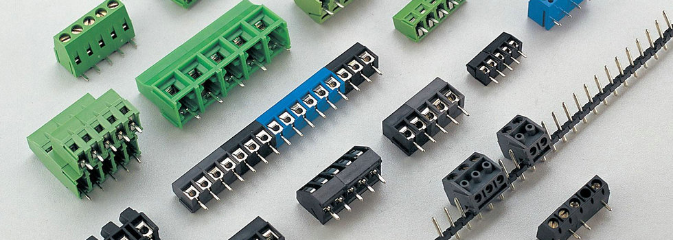
Some PCBs may incorporate specialized components such as sensors, connectors, or RF modules, which require specific knowledge for identification and troubleshooting. Familiarizing yourself with these components can enhance your ability to work with diverse electronic systems.
Whether you're a beginner in the field of electronics or an experienced professional, these tips and resources for identifying components on a circuit board will be valuable assets. By gaining a deep understanding of PCB layout, the characteristics of common components, and utilizing the right tools and resources, you can troubleshoot, repair, and design electronic circuits more effectively. Continual learning and practice throughout your exploration of the electronic world will continually enhance your skills. Wishing you success in the field of electronics!